
User Manual
5x2 HDBaseT 3.0 KVM Multiview HDMI & USB-C Switcher with Dante
Model PT-PSW-52KVM
Designed in Germany
| © 2023 PureLink GmbH All rights reserved. | Version V1.0 |
Preface
Read this user manual carefully before using this product. Pictures shown in this manual are for reference only. Different model layouts and specifications are subject to the physical product. This manual is for operation instructions only, not for any maintenance usage.
In the constant effort to improve our product, we reserve the right to make changes in functions or parameters without prior notice or obligation.
Trademarks
Product model and logo are trademarks. Any other trademarks mentioned in this manual are acknowledged as the properties of the trademark owner. No part of this publication may be copied or reproduced without the prior written consent.
FCC Statement

REACH | 1907/2006/EU
ROHS | 2011/65/EU
PureLink hereby declares that this product PureTools PT-PSW-52KVM complies with Directives 1907/2006/EU und 2011/65/EU.
EMC / LVD (Electro Magnetic Compatibility / Low Voltage Directive)
PureLink GmbH hereby declares that this product PureTools PT-PSW-52KVM complies with Directives 2014/30/EU and 2014/35/EU. The full text of the EU Declaration of Conformity is available at the following Internet address:
http://www.purelink.de/ce/ 4251364741542_CE.pdf

SAFETY PRECAUTIONS
To ensure the best from the product, please read all instructions carefully before using the device. Save this manual for further reference.
- Unpack the equipment carefully and save the original box and packing material for possible future shipment.
- Follow basic safety precautions to reduce the risk of fire, electrical shock and injury to persons.
- Do not dismantle the housing or modify the module. It may result in electrical shock or burn.
- Using supplies or parts not meeting the products’ specifications may cause damage, deterioration, or malfunction.
- Refer all servicing to qualified service personnel.
- To prevent fire or shock hazard, do not expose the unit to rain, moisture or install this product near water.
- Do not put any heavy items on the extension cable in case of extrusion.
- Do not remove the housing of the device as opening or removing housing may expose you to dangerous voltage or other hazards.
- Install the device in a place with fine ventilation to avoid damage caused by overheat.
- Keep the module away from liquids.
- Spillage into the housing may result in fire, electrical shock, or equipment damage. If an object or liquid falls or spills on to the housing, unplug the module immediately.
- Do not twist or pull by force ends of the optical cable. It can cause malfunction.
- Do not use liquid or aerosol cleaners to clean this unit. Always unplug the power to the device before cleaning.
- Unplug the power cord when left unused for a long period of time.
- Information on disposal for scrapped devices: do not burn or mix with general household waste, please treat them as normal electrical wastes.
1. Product Introduction
1.1 Introduction
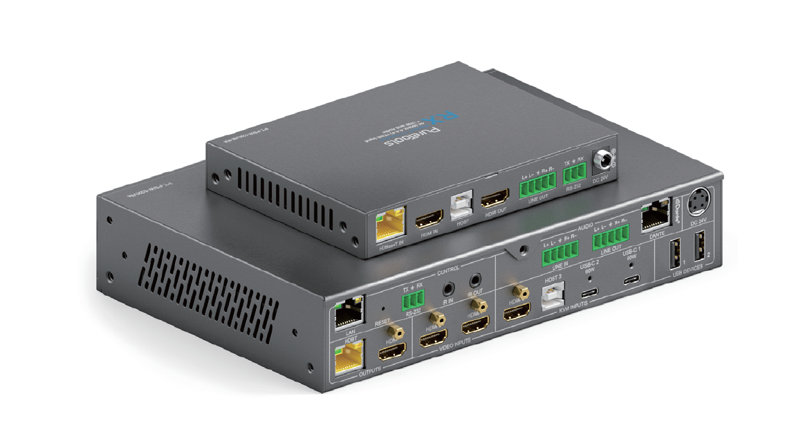
The PT-PSW-52KVM is an 18Gbps seamless presentation switcher that offers 2x HDMI inputs, 1x HDMI + USB-B input, 2x USB-C inputs (DP Alt mode, USB 2.0, 100Mbps Ethernet and 60W charging), 1x HDMI output and 1x HDBT mirrored output. It utilizes the HDBaseT 3.0 protocol and supports PoH for remote powering the RX and can extend uncompressed signals up to a distance of 70m (4K@30Hz 4:4:4) or 40m (4K@60Hz 4:4:4) via a single CAT6A (S/FTP) cable. This presentation switcher supports single full screen or various multi-view display modes (Single/PIP/PBP/Triple/Quad). It has USB 2.0 local KVM switching and local Hub/HDBT USB pass-through function (from TX to RX). It also supports bi-directional RS-232 and IR control signal pass-through function.
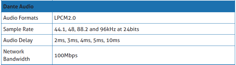
This presentation switcher also features an analogue audio input, an analogue audio output, as well as a Dante 2x2 audio input and output. It also has a built-in 3x3 audio matrix with independent audio EQ/volume/delay adjustment.
1.2 Feature
- HDMI 2.0b, HDCP 2.2 and DP 1.2 compliant
- 18Gbps video bandwidth with video resolution up to 4K@60Hz (4:4:4)
- Uncompressed 4K@60Hz (4:4:4) over HDBT 3.0 up to 40m via single CAT6A (F/FTP)
- Uncompressed 1080P&4K@30Hz (4:4:4) over HDBT 3.0 up to 70m via a CAT6A (S/FTP)
- 5 multi-view layout display modes: Single/PIP/PBP/Triple/Quad
- Supports seamless switching (single screen) and fast switching (multi-view) function
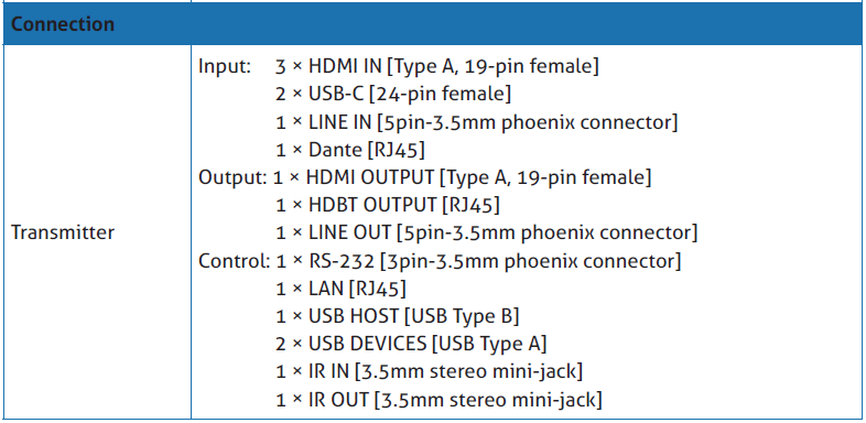
- Input: 2x USB-C, 3x HDMI, 1x Analog audio, 1x Dante 2ch
- Output: 1x HDMI and 1x HDBT mirrored, 1x Analog audio, 1x Dante 2ch
- HDMI and HDBaseT (PoH) outputs (Mirrored)
- Dante 2x2 audio input and output
- USB-C supports DisplayPort Alt mode for A/V, USB 2.0, 100M Ethernet and 60W charging
- Local USB 2.0 KVM switching and extending USB 2.0 over HDBT 3.0
- Signal input supports manual switching and automatic switching modes
- Support for analogue/Dante audio embedding, analogue/Dante audio deembedding
- CEC/RS-232 control for external devices ON/OFF
- Advanced EDID management
- Flexible control via front panel buttons, IR remote, RS-232, TCP/IP or Web GUI
- Supports unidirectional TX > RX PoH
1.3 Package List
- 1x 18Gbps Seamless Presentation Switcher
- 1x HDBaseT Receiver
- 1x IR Blaster Cable (1.5 meters)
- 1x IR Wideband Receiver Cable (1.5 meters)
- 2x 3pin-3.5mm Phoenix Connector (male)
- 3x 5pin-3.5mm Phoenix Connector (male)
- 4x Mounting Ear
- 8x Machine Screw
- 1x 24V/8A Desktop Power Supply
- 1x AC Power Cord (1.5 meters)
- 1x IR Remote
- 1x User Manual
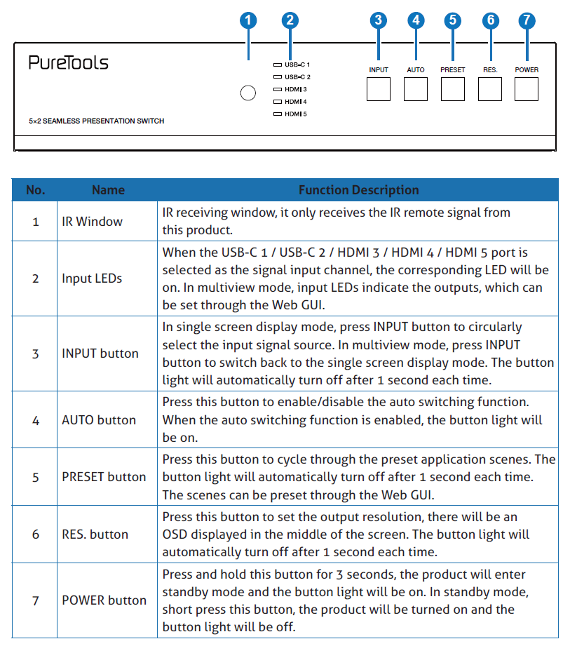
2. Panel Description
2.1 Switcher Panel
Front Panel
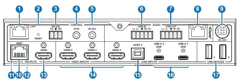
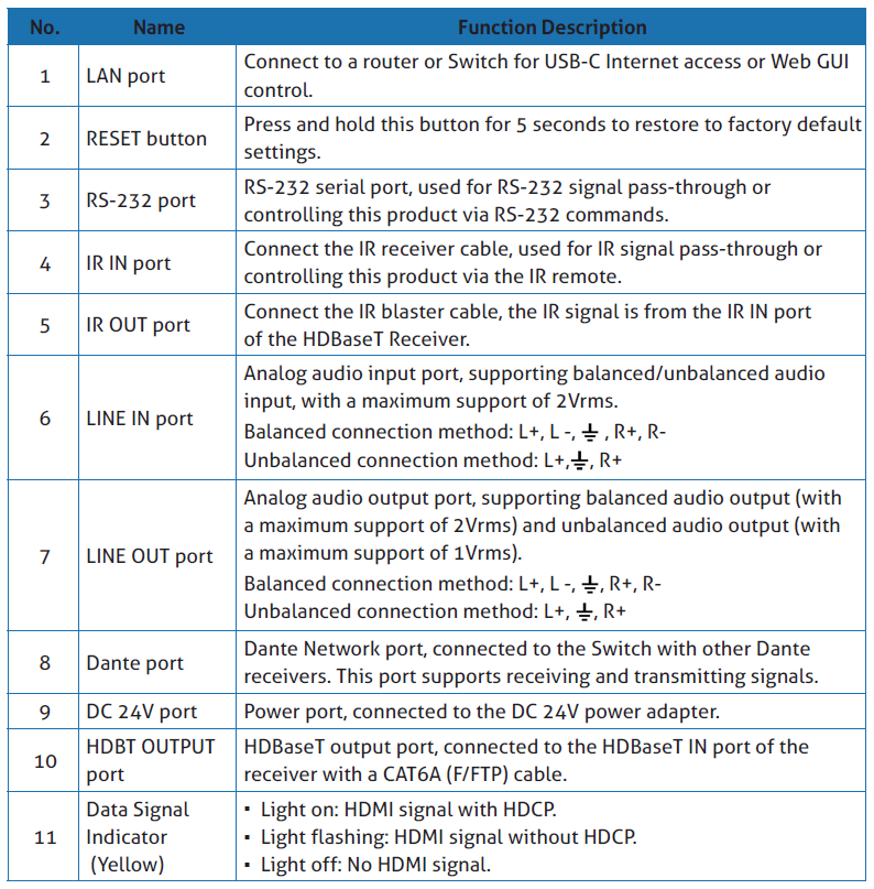
Rear Panel
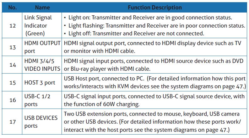
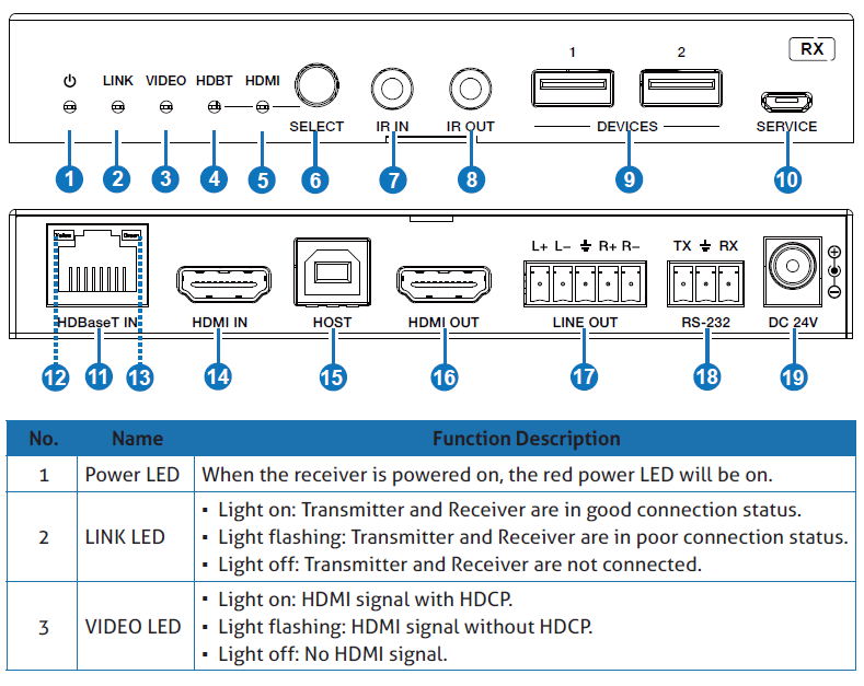
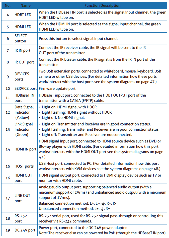
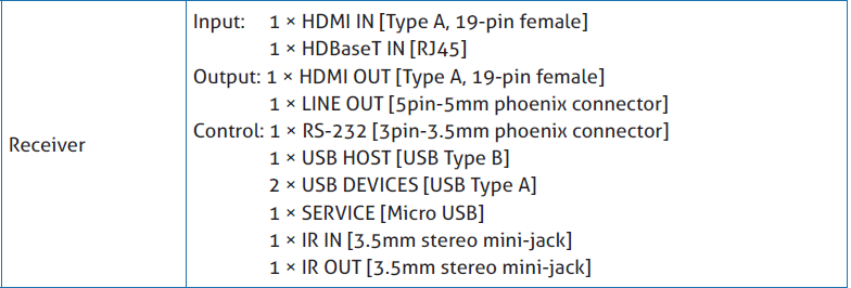
2.2 HDBaseT Receiver Panel
2.3 IR Cable Pin Assignment
The pin assignment of the IR Receiver cable and IR Blaster cable is as below:

Note: When the angle between the IR receiver and the remote control is ± 45 °, the transmission distance is 0-5 meters; when the angle between the IR receiver and the remote control is ± 90 °, the transmission distance is 0-8 meters.
3. IR Remote
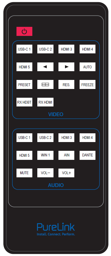 |
Power button: Press this button to power on the switcher or set it to standby mode.
VIDEO buttons: USB-C 1 / USB-C 2 / HDMI 3 / HDMI 4 / HDMI 5: Press these buttons to select input source in single screen display mode, and the corresponding input LED on the front panle will light in green.
◄ ►: Press these buttons to circularly select the last or next input source in single screen display mode.
AUTO: Press this button to enable/disable the auto switching function.
PRESET: Press this button to cycle through the preset application scenes.
Multiview display mode switching button. Short press this button to circularly select: Single - PIP - PBP - Triple - Quad.
RES.: Press this button to cycle through the output resolution.
FREEZE: Press this button to freeze/unfreeze the screen.
RX HDBT: Press this button to select the HDBaseT IN port as the signal source input channel of the receiver.
RX HDMI: Press this button to select the HDMI IN port as the signal source input channel of the receiver.
AUDIO buttons: USB-C 1 / USB-C 2 / HDMI 3 / HDMI 4 / HDMI 5 / WIN 1 / AIN / DANTE: Press these buttons to select the audio input channel for the HDMI/HDBT output.
Mute: Press this button to mute / unmute the audio of Master Out.
VOL-, VOL+: |

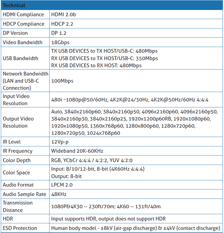
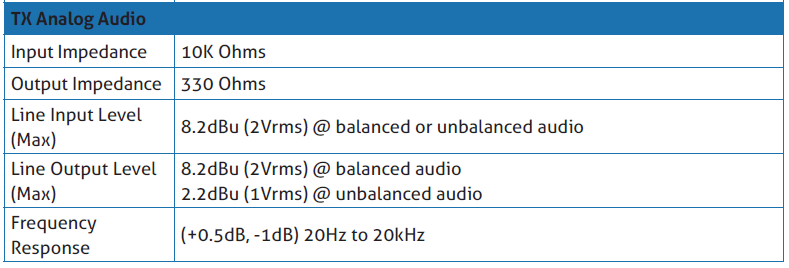
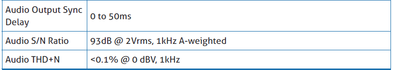
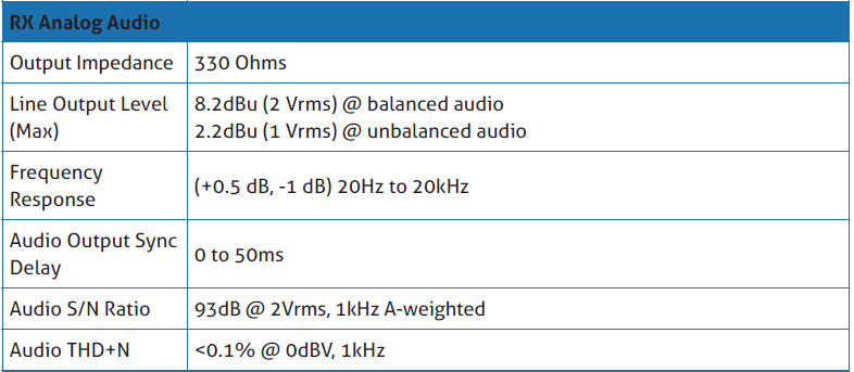
4. Specifications
5. Web GUI User Guide
The presentation switcher can be controlled by Web GUI. The operation method is shown as below:
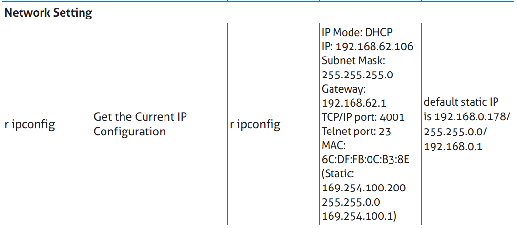
Step 1: Get the current IP Address.
The default IP address is 192.168.0.178 (when the system is not connected to a router). You can get the current Matrix IP address via RS-232 command control. Send the ASCII command “r ip addr” through a Serial Command tool, then you’ll get the current IP address (The IP address is variable, depending on what the specific machine returns).
For the details of RS-232 control, please refer to “RS-232 Control Command”.
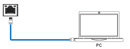
Step 2: Connect the LAN port of the presentation switcher to a PC with an UTP cable (as shown in the following figure), and set the IP address of the PC to be in the same network segment with the presentation switcher.
After entering the Web GUI page, there will be a Login interface, as shown below:

The default usernames and passwords are as below:
Username user admin
Password user admin
Enter the username “user” and the password “user”, then click the “Login” button to enter the User page.
User Page
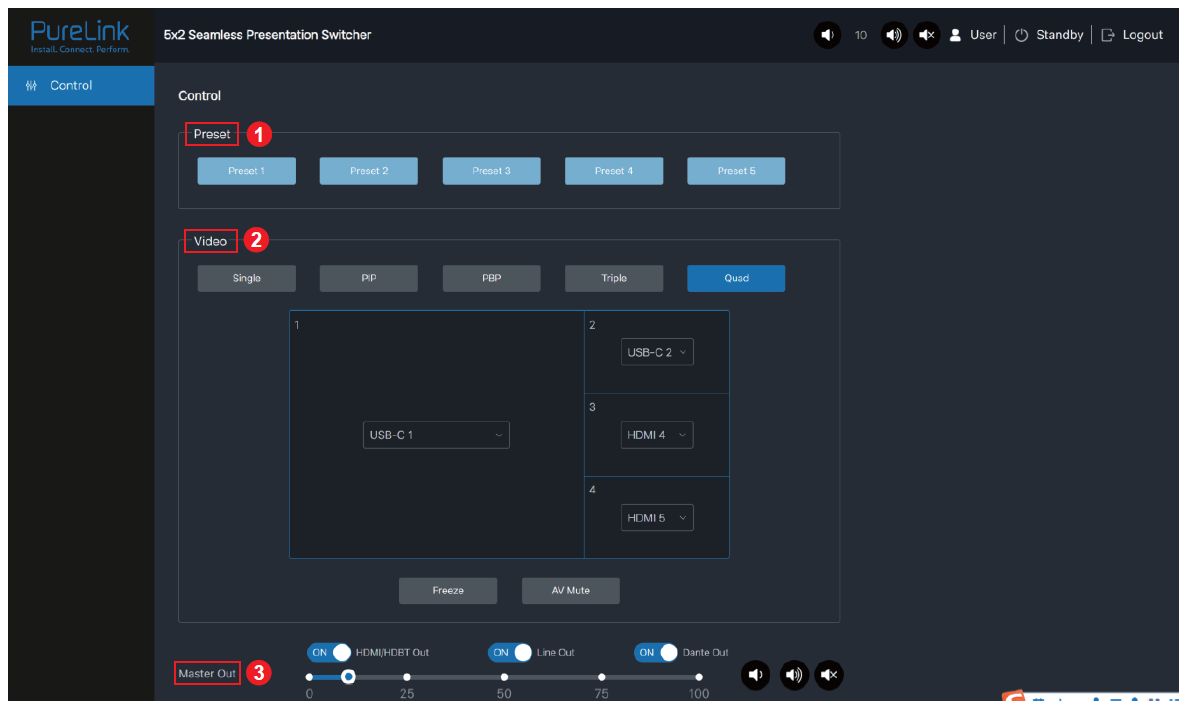
You can do the following operations on the User page:
- Preset: Recall the preset application scenes.
- Video: Set the multiview display mode, select input source for each screen, freeze the screen or mute the audio.
- Master Out: Set the audio volume or mute/unmute the audio for Master Out. You can respectively turn on/off the HDMI/HDBT Out, Line Out or Dante Out.
Enter the username “admin” and the password “admin”, then click the “Login” button to enter the Information page of the Admin interface.
Information Page

The Information page provides basic information about the model name, software version, IP information and the current machine temperature.
Besides, you can do the following operations on each page of the Admin interface.
- Display and set the audio volume of Master Out. Click the volume icons to increase/decrease the audio volume of Master Out, or click the mute icon to mute/unmute the audio of Master Out. When muted, the mute icon displays red.
- Display the current username (User or Admin).
- Click the power icon to power on the switcher or set it in standby mode.
- Click the logout icon to logout and return to the login interface.
Status Page

The Status page displays the input & output port connection status, input & output resolution, color space, color depth and HDCP.
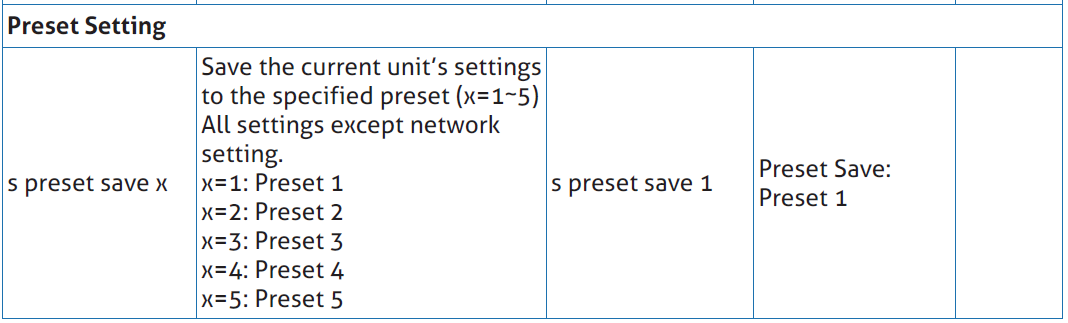
Preset Page
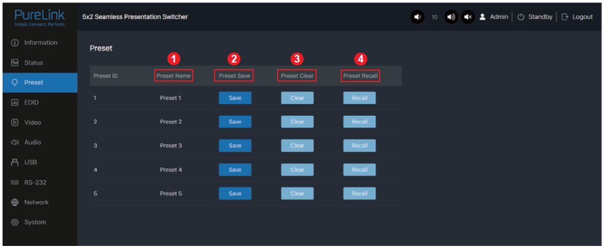
You can set up to 5 preset scenes on the Preset page.
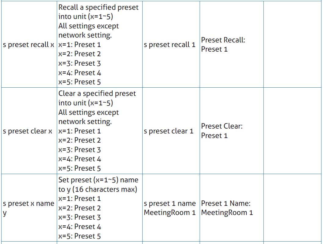
- Preset Name: You can name the preset scene.
- Preset Save: Click the Save button to save the scene.
- Preset Clear: Click the Clear button to clear the saved scene.
- Preset Recall: Click the Recall button to recall the saved scene.
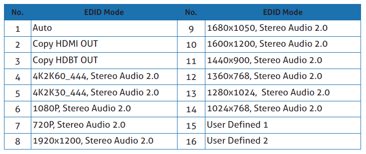
EDID Page
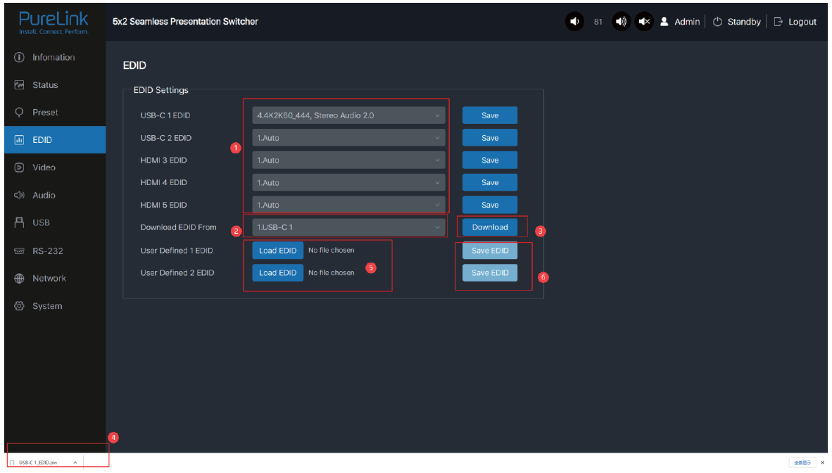
You can do the following operations on the EDID page.
- Click the drop-down list to set EDID for each input port. The EDID list is as below.
- Click the drop-down list to select USB-C 1 \ USB-C 2 \ HDMI 3 \ HDMI 4 \ HDMI5 \ HDMI OUT \ HDBT OUT for EDID download.
- Click the Download button to download EDID and generate a .bin file.
- Display the downloaded EDID .bin file.
- Click the Load EDID button to download user-defined EDID. Please note that only bin files are supported.
- Click the Save EDID button to save the user-defined EDID.
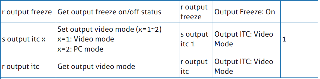
Video Page

Switch Mode
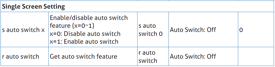
- Auto Switch: You can turn on/off the auto switching function.
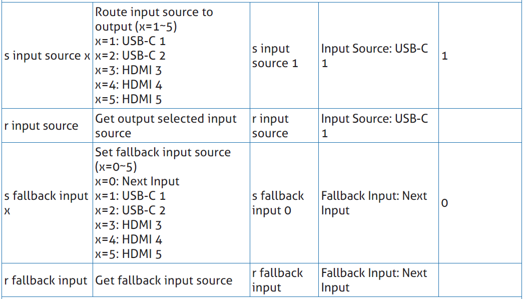
- Fallback Input: Click the drop-down list to select Auto \ USB-C 1 \ USB-C 2 \ HDMI 3 \ HDMI 4 \ HDMI 5 as the signal source of Fallback input. When the auto switching function is turned on and the current input source is disconnected, the Fallback input signal source will be selected automatically. When the Fallback input is set to be Auto, the switcher will detect and switch to the signal with the auto switching sequence of USB-C 1 > USB-C 2 > HDMI 3 > HDMI 4 > HDMI 5.
Note: The auto switching function is available only in single screen display mode.
Window layout
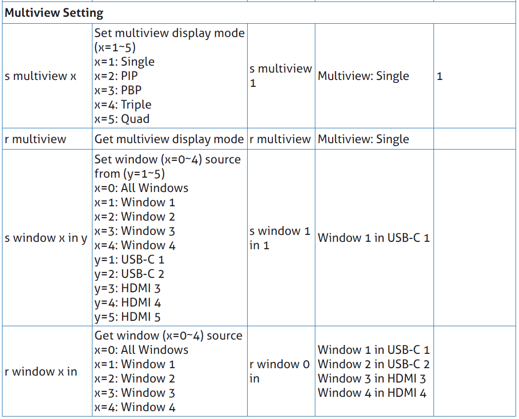
- Window layout: Click the drop-down list to select the display mode (1.Single \ 2.PIP \ 3.PBP \ 4.Triple \ 5.Quad).
- Freeze: You can freeze the screen.
- AV Mute: You can mute the audio and video.
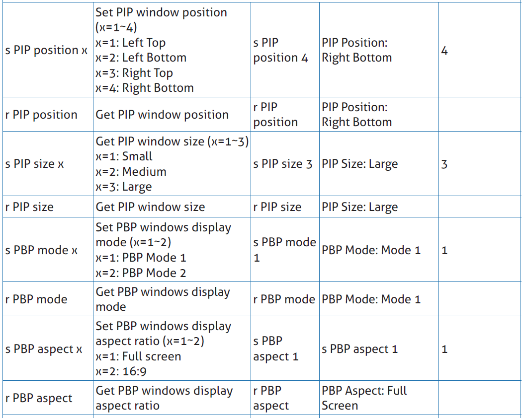
- PIP Position: Click the drop-down list to select the display position in PIP display mode.
- PIP Size: Click the drop-down list to select the display size in PIP display mode.
- Display Mode: Click the drop-down list to select the display mode in PBP \ Triple \ Quad display mode.
- Display Aspect: Click the drop-down list to select the display aspect in PBP \ Triple \ Quad display mode.
- Border: Click the drop-down list to select the border and border color in PBP \ Triple \ Quad display mode.
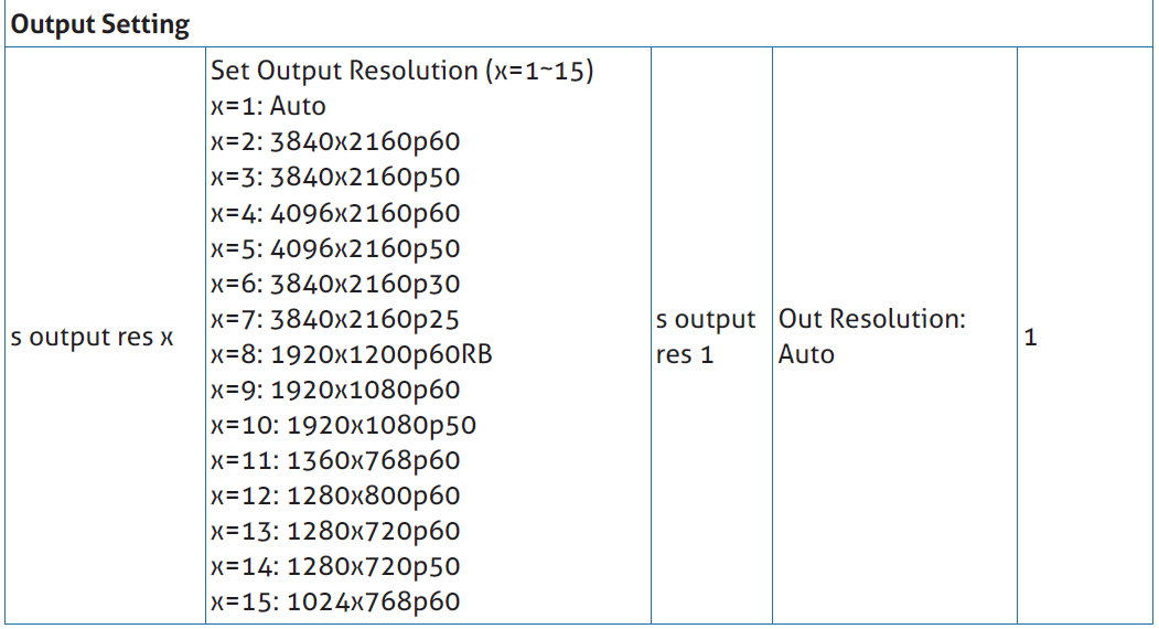
Output Setting
-
Resolution: Click the drop-down list to select the output resolution. The output resolution list is as following.
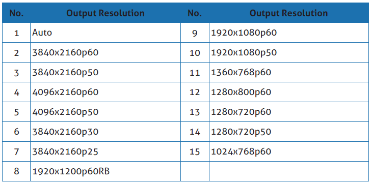
Note: When the output resolution is set to Auto, the switcher will output the matching resolution based on the EDID of the back-end TV.
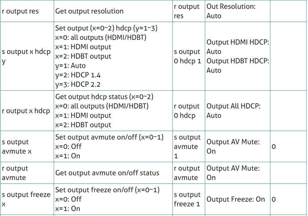
- HDMI HDCP: Click the drop-down list to select the HDMI HDCP version.
-
HDBT HDCP: Click the drop-down list to select the HDBT HDCP version.
After setting up, click “Save” to take effect.
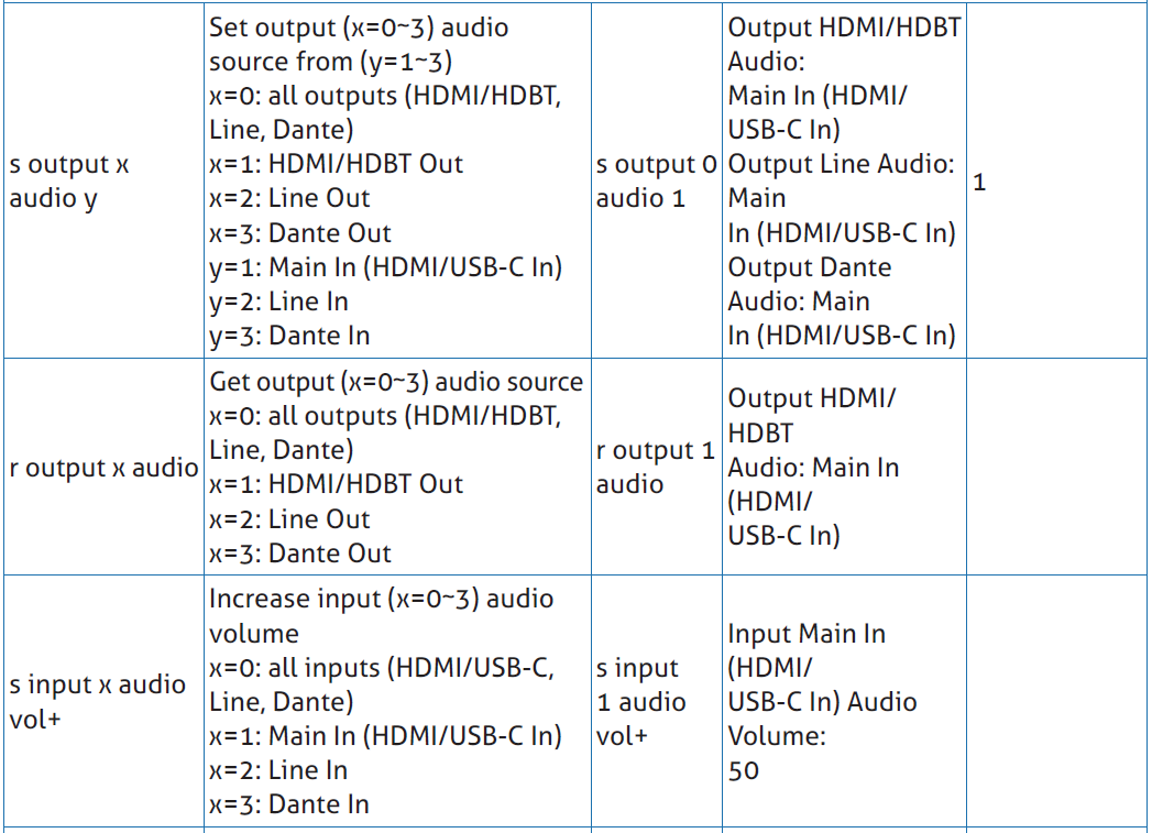
Audio Page
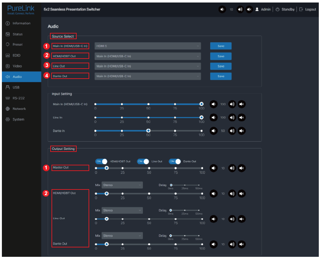

Source Select
- Main In: Click the drop-down list to select the signal source for Main In.
- HDMI / HDBT Out: Click the drop-down list to select the signal source for HDMI / HDBT Out.
- Line Out: Click the drop-down list to select the signal source for Line Out.
-
Dante Out: Click the drop-down list to select the signal source for Dante Out.
After setting up, click “Save” to take effect.
Input Setting
You can respectively set the output volume or mute/unmute the audio for Main In (HDMI/USB-C In)\Line In\Dante In.
Output Setting
- Master Out: You can respectively set the output volume or mute/unmute the audio for HDMI/HDBT Out\Line Out\Dante Out, or set together when turning on three options synchronously.
- HDMI / HDBT Out \ Line Out \ Dante Out 3: Click the drop-down list of Mix to select the audio output channel for HDMI/HDBT Out\Line Out\Dante Out 3. You can set the delay, increase/decrease the audio or mute/unmute the audio.
GEQ Setting
- Output: Click the drop-down list to select the output channel.
-
Equalizer: Click the drop-down list to set the equalizer.
Flat: Set all EG to 0db.
Custom1: Set EQ for custom 1.
Custom2: Set EQ for custom 2.
Custom3: Set EQ for custom 3.
Custom4: Set EQ for custom 4.
Custom5: Set EQ for custom 5.
USB Page
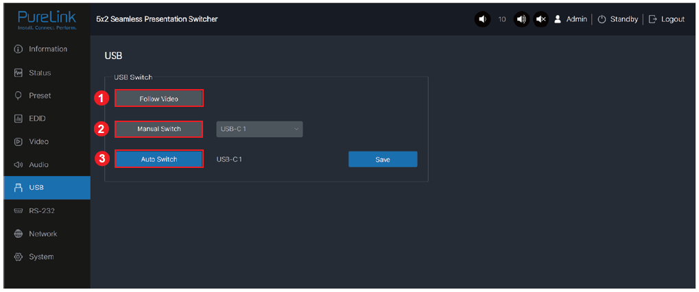
USB Switch
- Follow Video: Click this button to set the USB transmission follow the video. It will follow the video output of window 1 in multiview mode.
- Manual Switch: Switch to USB-C 1\USB-C 2\Host 3 manually.
-
Auto Switch: Detect and switch to USB-C 1\USB-C 2\Host 3 automatically.
After setting up, click “Save” to take effect.
RS-232 Page
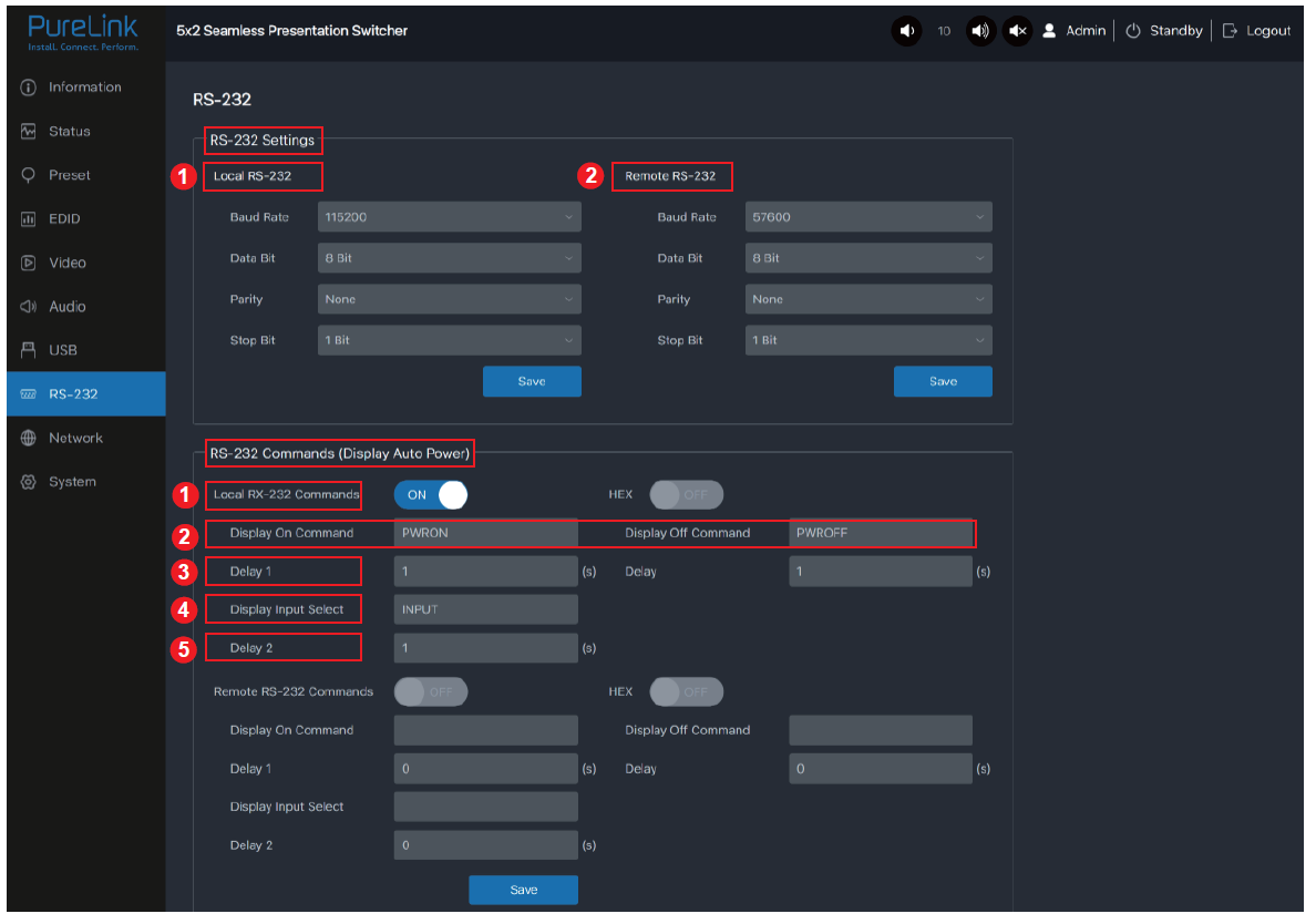
RS-232 Settings
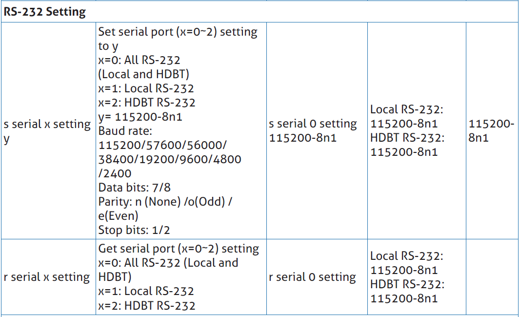
- Local RS-232: You can set the Baud Rate, Data Bit, Parity and Stop Bit for the RS-232 port of the transmitter.
- Remote RS-232: You can set the Baud Rate, Data Bit, Parity and Stop Bit for the RS-232 port of the receiver.
RS-232 Commands (Display Auto Power)
- Local/Remote RS-232 Commands: Click You can turn on/off the local/remote RS-232 commands and hex.
- Display On/Off Command: You can input the display on/off command of the device.
- Delay 1: You can set the delay time for the next action (such as send the Display Input Select command).
- Display Input Select: You can input the command of switching the input channel for the display device.
-
Delay 2: You can set the delay time for the next action after sending the Display Input Select command.
After setting up, click “Save” to take effect.
Network Page
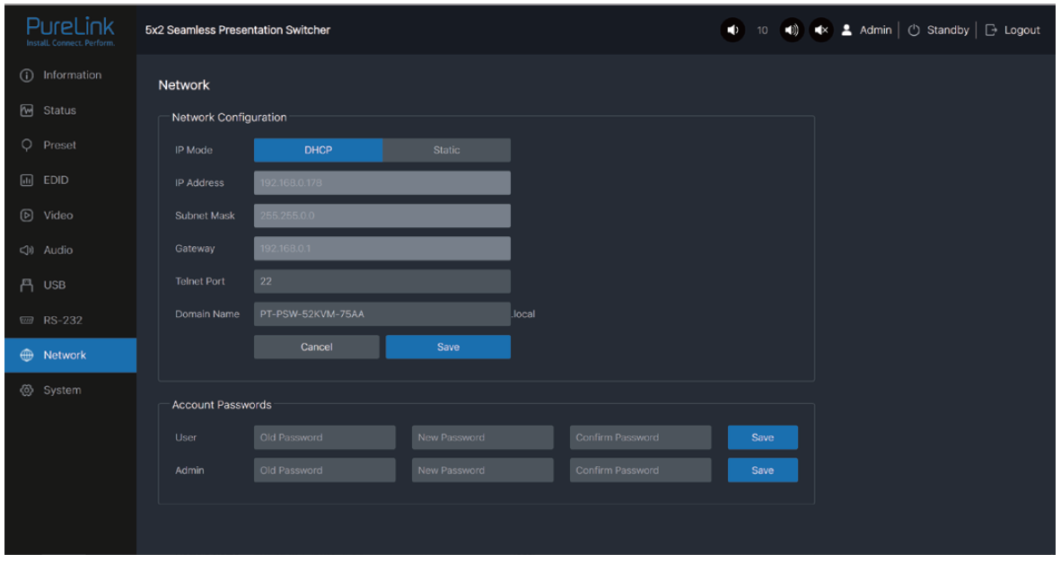
Network Configuration: You can set the IP Mode (DHCP/Static), IP Address, Subnet Mask. Gateway, Telnet Port and Domain Name.
Note: The Domain Name “PT-PSW-52KVM-75AA.local” can be used to login the Web GUI. Besides, you can modify the login password for User and Admin.
After setting up, click “Save” to take effect.
System Page
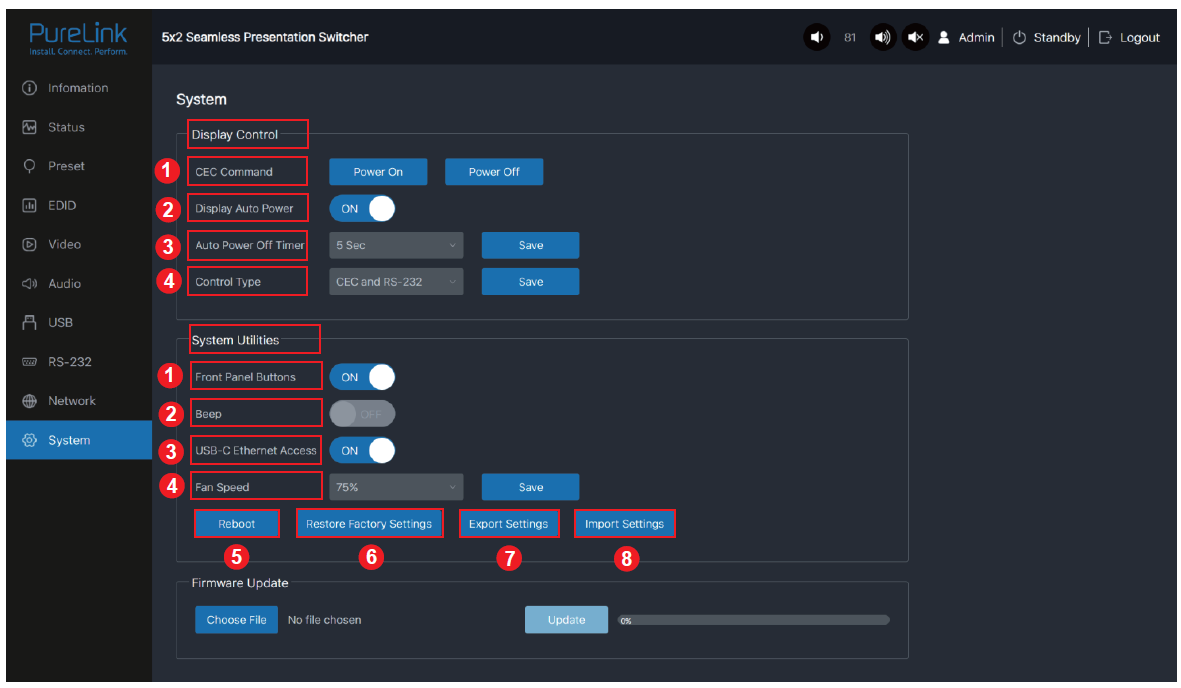
Display Control
- CEC Command: You can power on/off the CEC command.
- Display Auto Power: You can turn on/off the Display Auto Power. When it is set to ON, you can control the display device power on/off or switch the port based on the power status (power on/standby) or the signal input status of the transmitter by sending serial port or CEC Power On/Off command.
- Auto Power off Timer: You Click the drop-down list to select the delay time for sending the command to turn off the display device when the transmitter is in standby mode or there is no signal input.
- Control Type: Click the drop-down list to select the control type.
System Utilities
- Front Panel Buttons: Click “ON/OFF” to lock/unlock panel buttons. “On” indicates that panel buttons are available; “OFF” indicates panel buttons are unavailable.
- Beep: Click “ON/OFF” to turn on/off the beep.
- USB-C Ethernet Access: Click “ON/OFF” to turn on/off the Ethernet access function of USB-C.
- Fan Speed: Click the drop-down list to set the fan speed (25% / 50% / 75% / 100% / Auto).
- Reboot: Click “Reboot” to reboot the switcher.
- Restore Factory Settings: Click this button to restore the switcher to factory settings.
- Export Settings: Click this button to export configuration files.
- Import Settings: Click this button to import configuration files.
Firmware Update: You can update the software of MCU, Web, Scaler or receiver. Click “Choose File” to select the update file, then click “Update” to start update.
When the progress bar reaches 100%, the update is complete.
6. Dante Web GUI User Guide
There is a built-in Dante Web GUI for the presentation switcher. The operation method is shown as below:
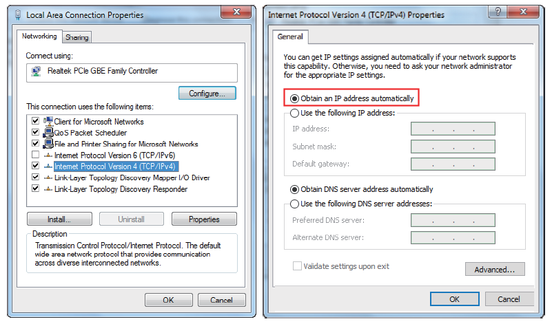
Step 1: Connect the presentation switcher and PC to the same Ethernet Switch with two Network cables.
Step 2: Set the Network connection setting of PC to be “Obtain an IP address Automatically”.
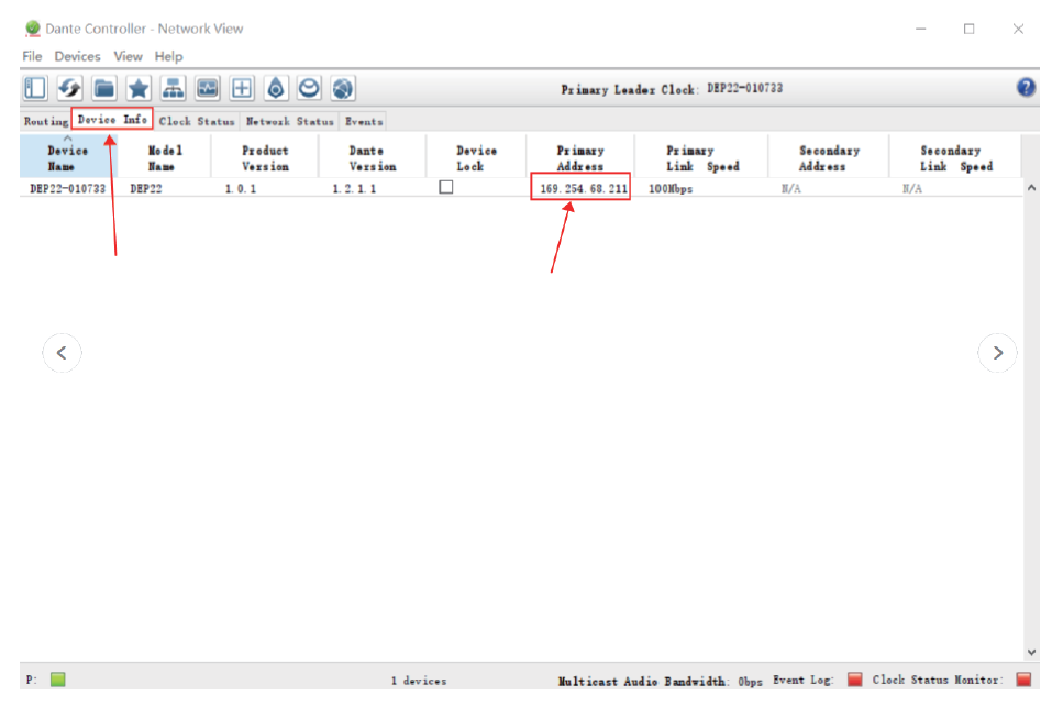
Step 3: Open the Dante Controller software on the PC, and find the Dante device on the Routing page, as shown in the figure below.

Step 4: Click the Device Info tab to check the IP address of the Dante device.
Step 5: Input the IP address of Dante device into your browser on the PC to enter the login interface of the Dante Web GUI.
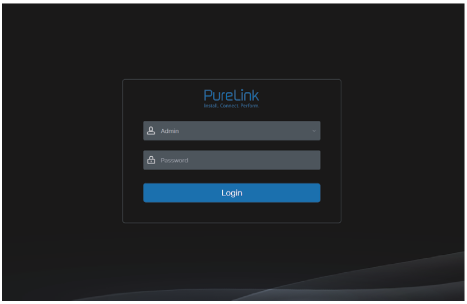
Step 6: Select the default username “Admin” and input the password “admin”, then click the “Login” button to enter the Information page of Dante Web GUI.
Information Page
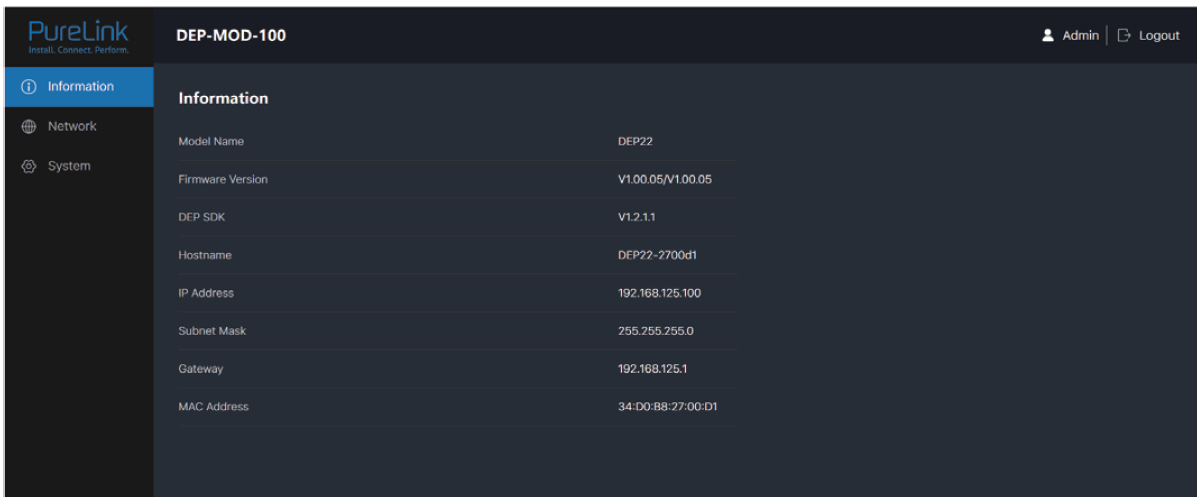
The Information page provides basic information about the model name, software version and IP information.
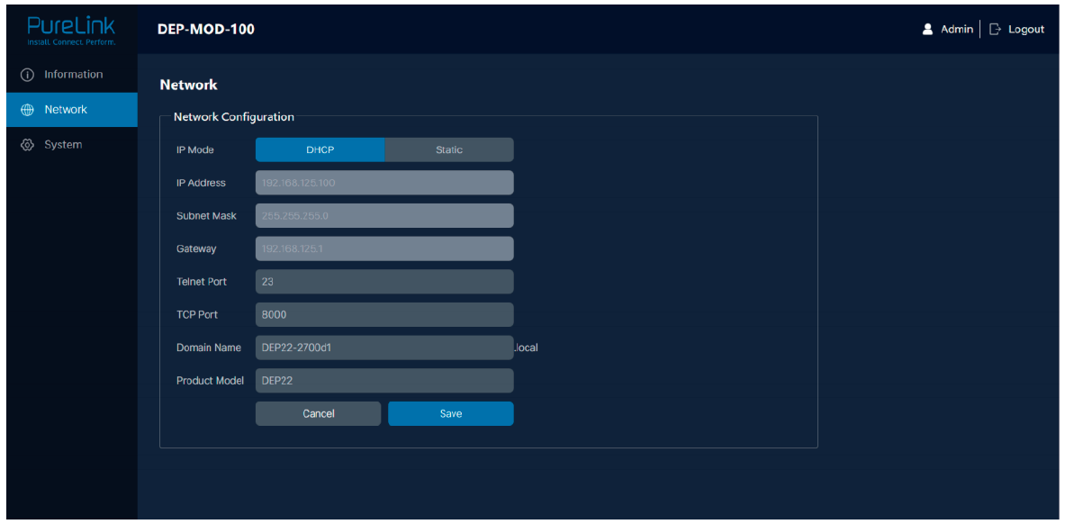
Network Page
On the Network page, you can set the IP Mode (DHCP/Static), IP Address, Subnet Mask, Gateway, Telnet Port, TCP Port and Domain Name. The product model can be modified.
Note: The Domain Name “DEP22-2700d1.local” can be used to login the Dante Web GUI.
System Page
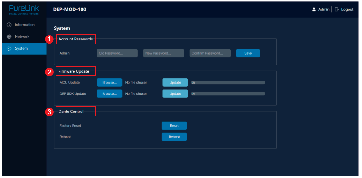
You can do the following operations on the System page:
- Account Passwords: You can modify the login password for Admin. After inputting the old password, new password and confirm password, click “Save” to take effect.
- Firmware Update: You can update the firmware and DEP SDK software. Click “Browse” to select the update file, and then click “Update”. When the progress bar reaches 100%, the update is complete.
- Dante Control: Click “Reset” to restore to factory settings. Click “Reboot” to reboot the device.
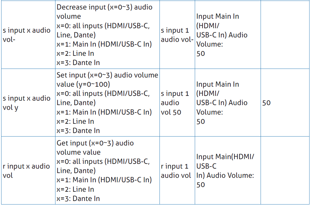
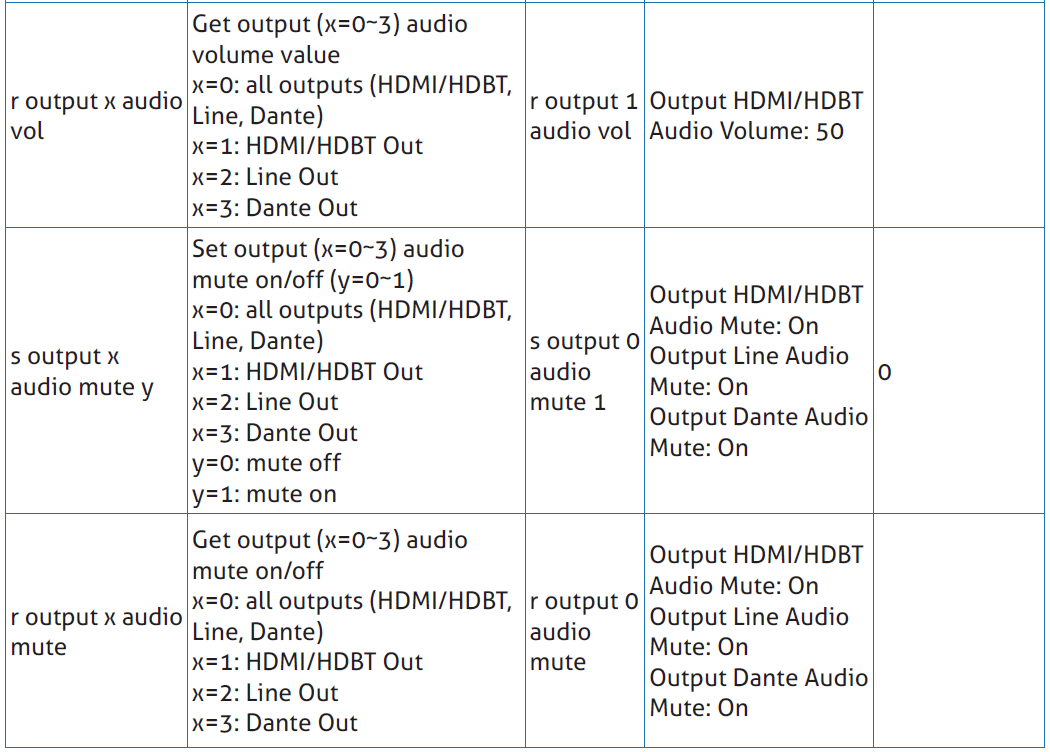
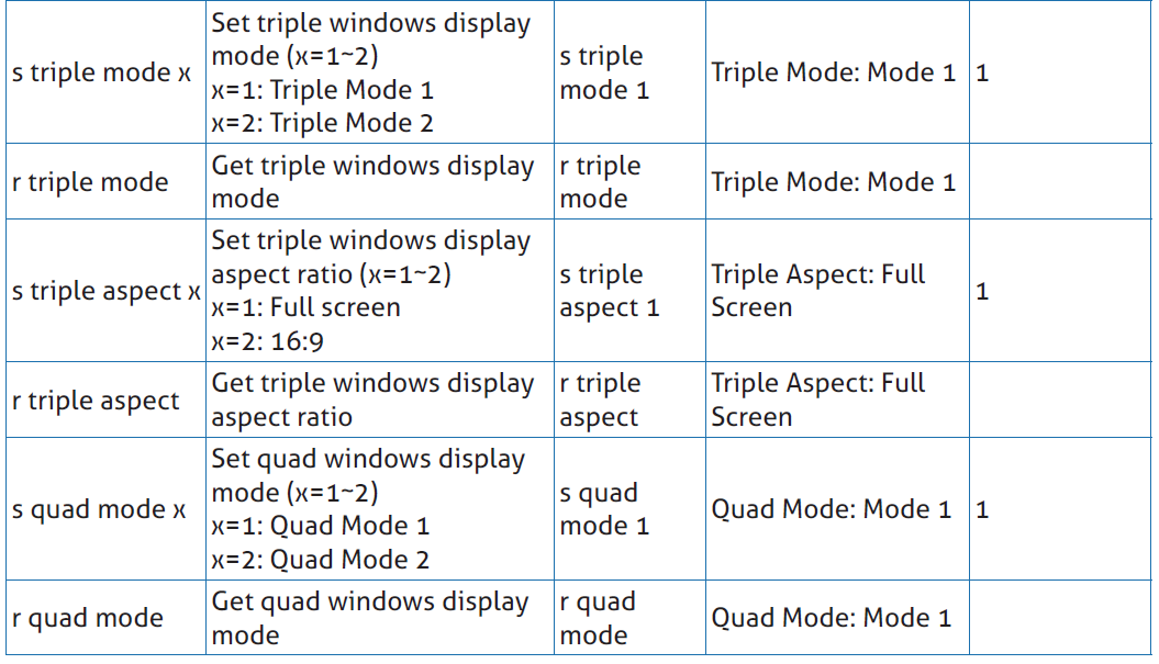
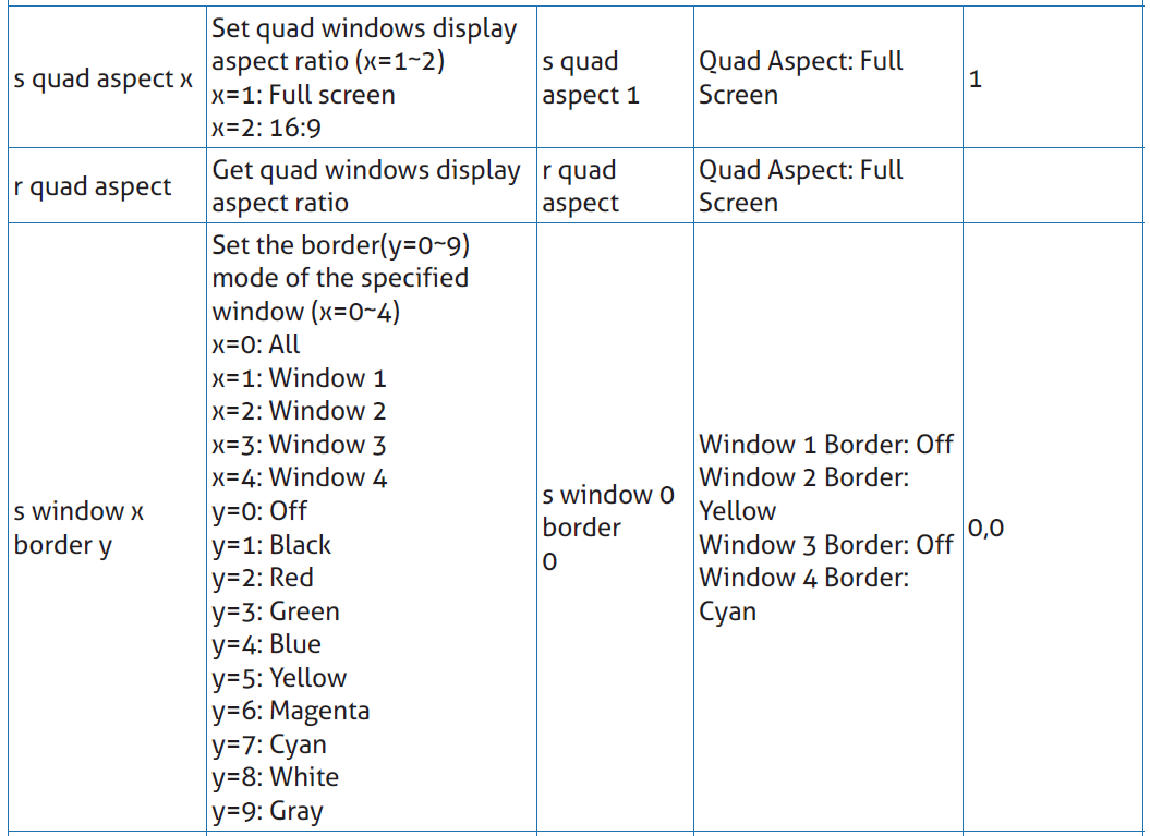
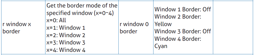
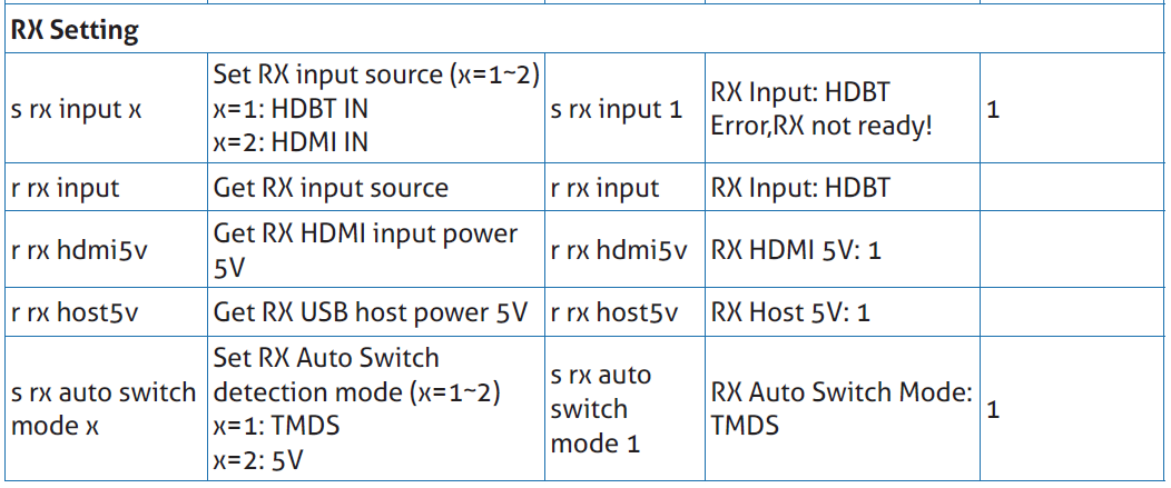
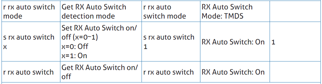
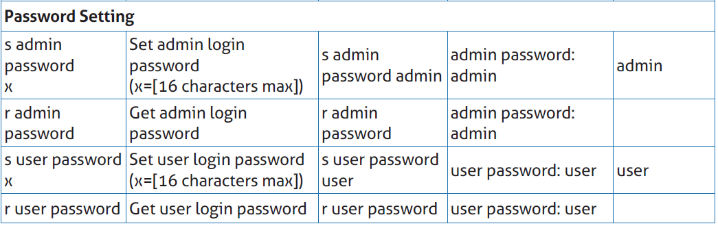
7. RS-232 Control Command
The product also supports RS-232 command control. Connect the RS-232 port of the PT-PSW-52KVM to the PureLink PTM-RS100 configurable RS232 cable (or other appropriate cable) and your control device. The DIP settings are as follows:
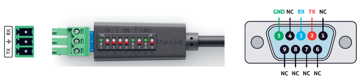
Then open a Serial Command tool on PC to send ASCII commands to control the product.
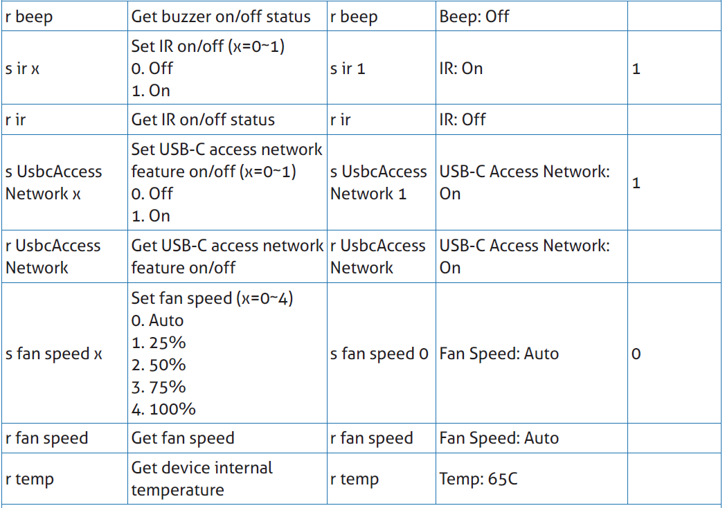
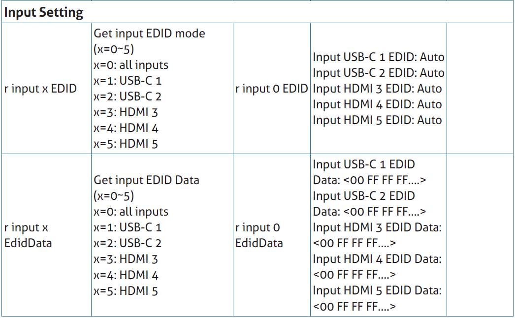
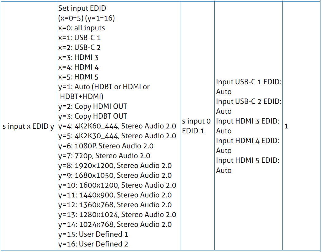
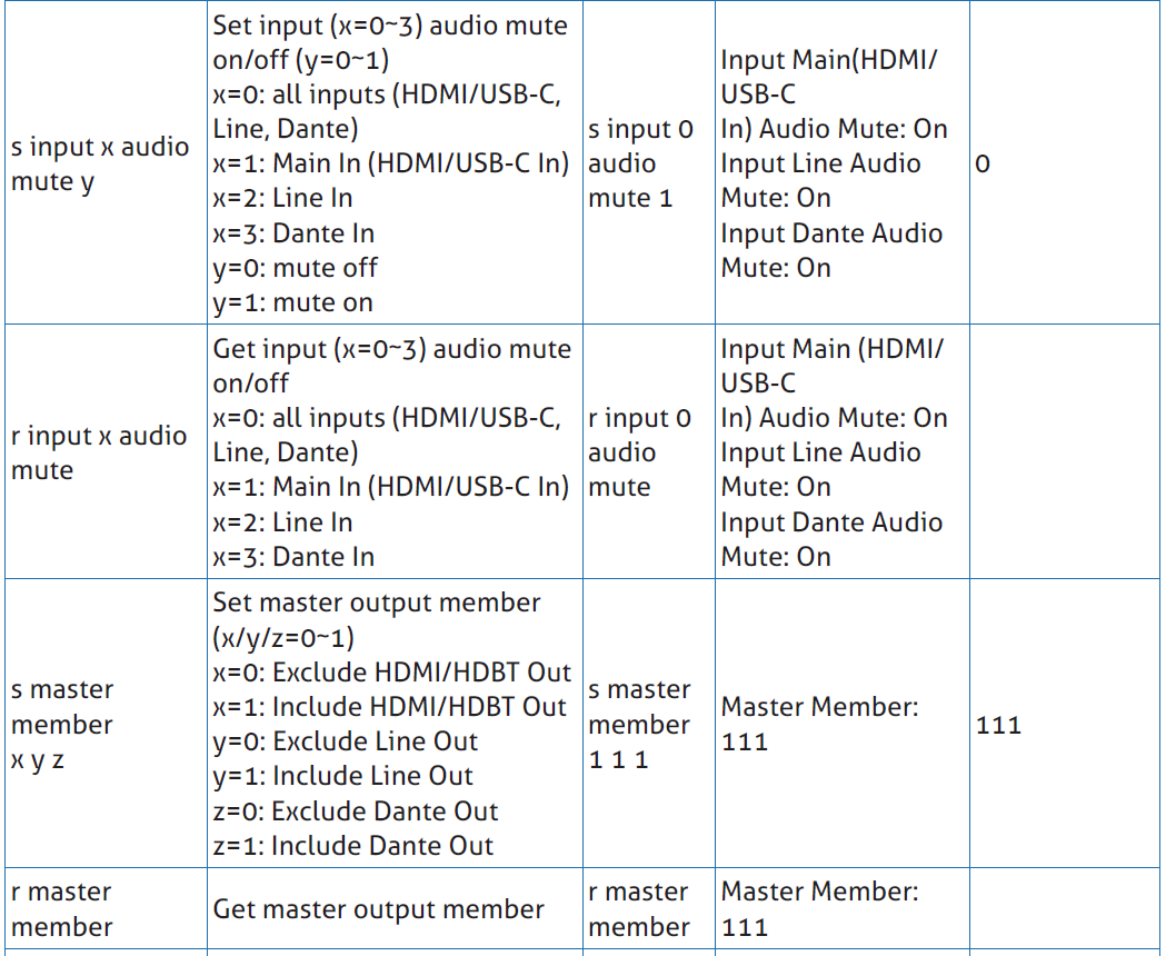
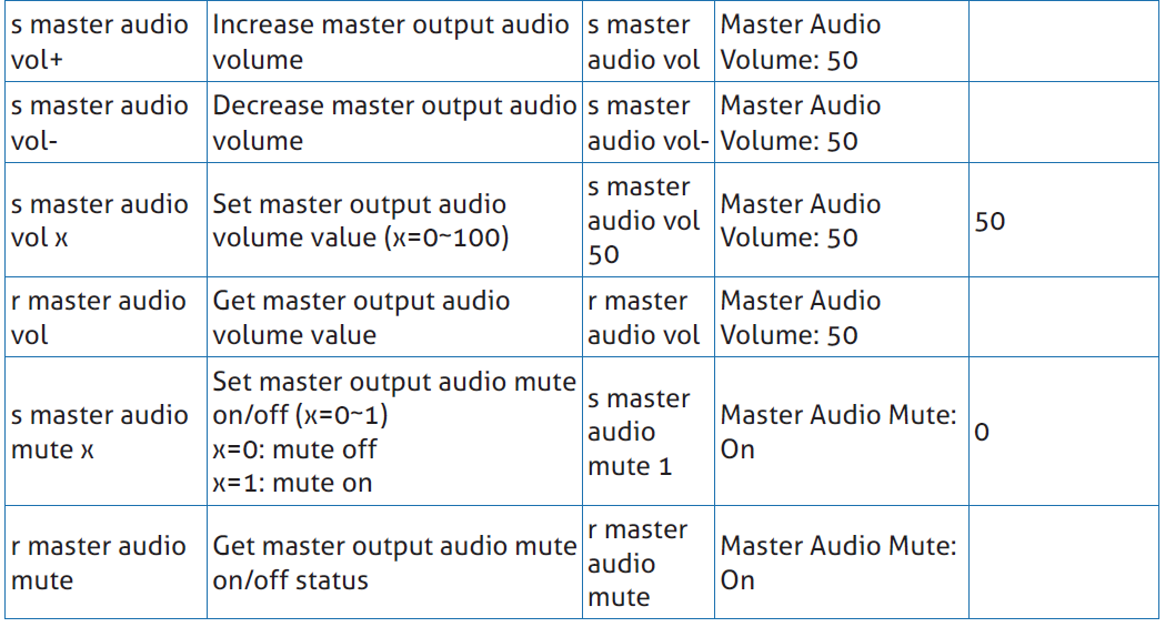
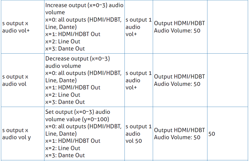
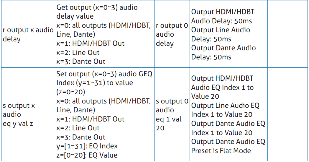
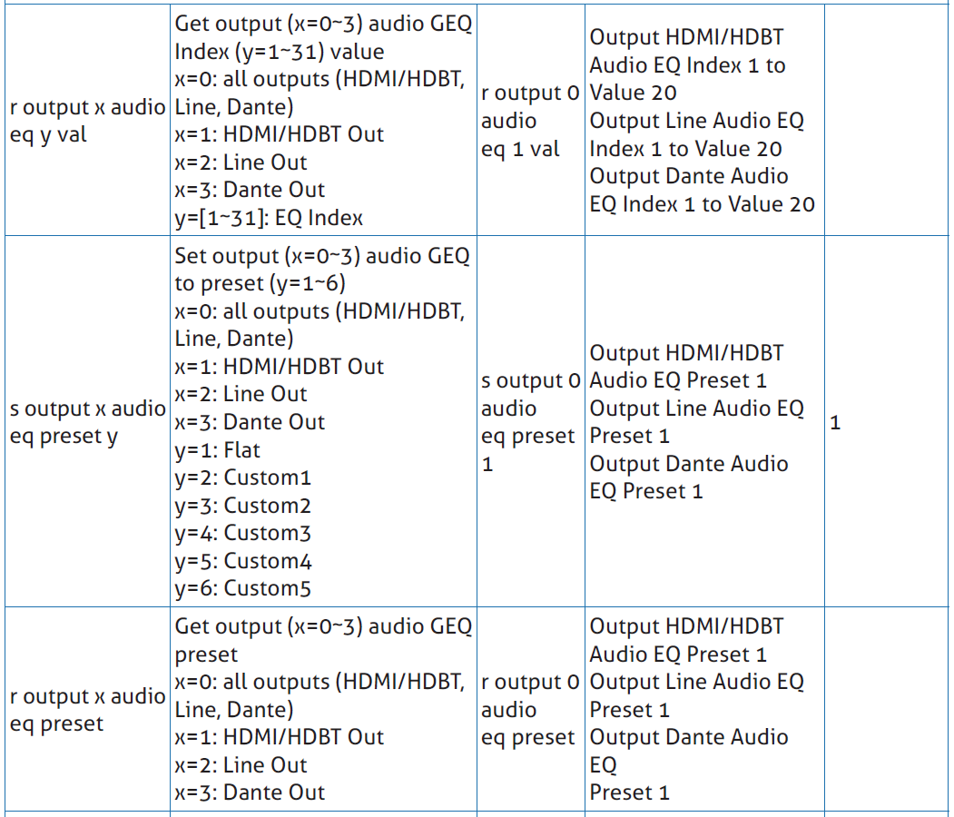
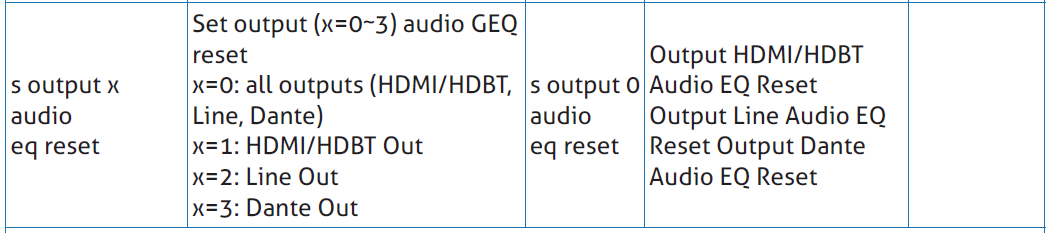
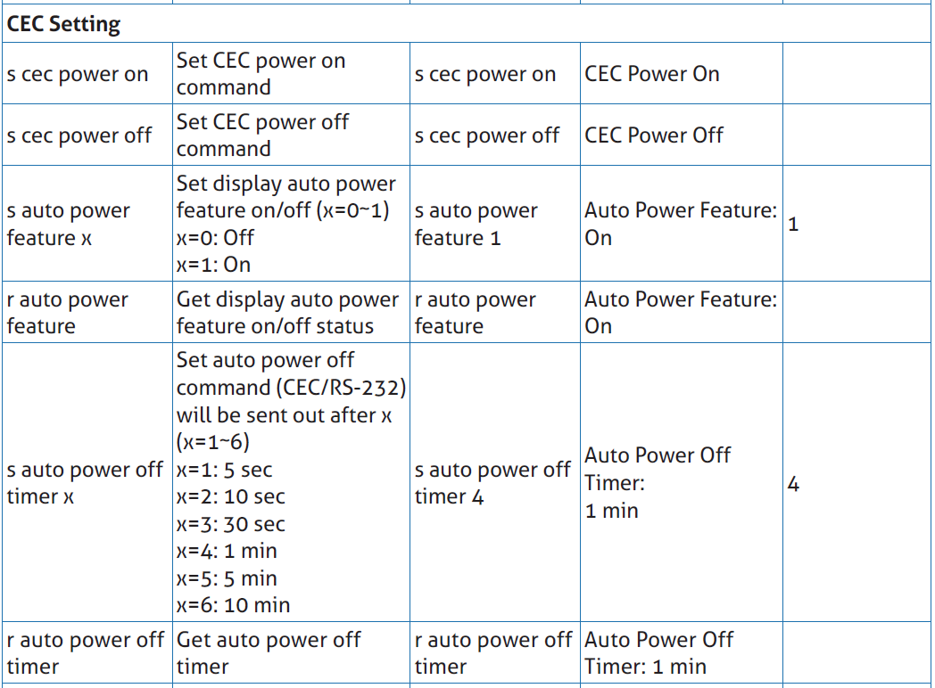
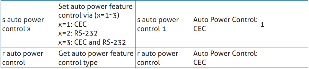
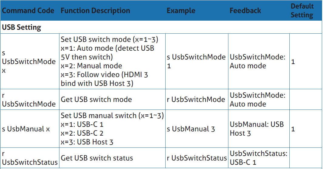
The ASCII command list about the product is shown as below.

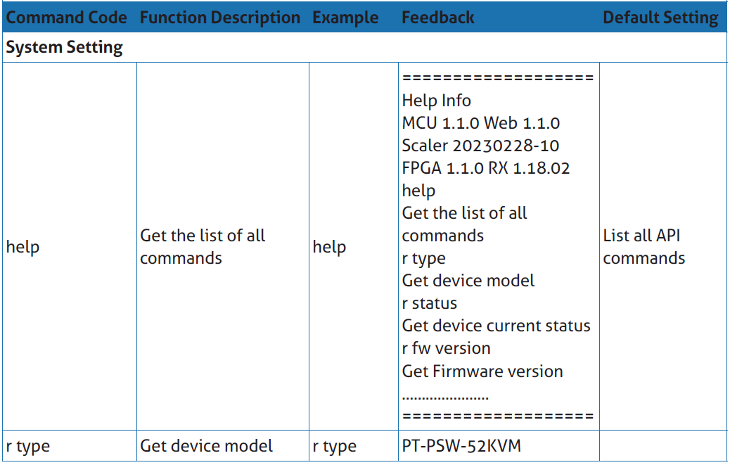
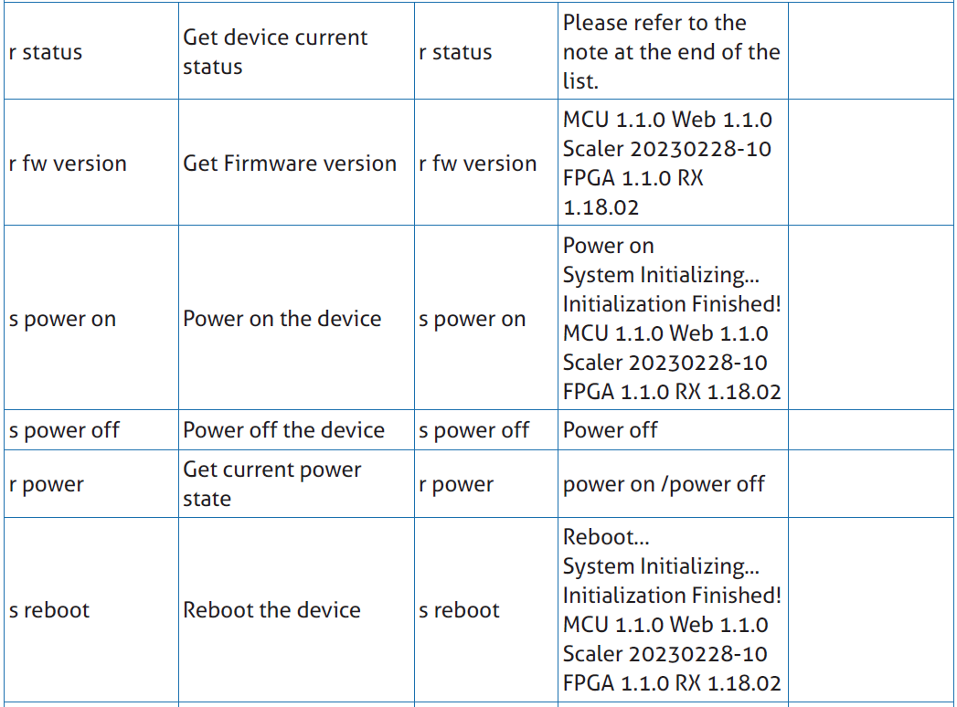
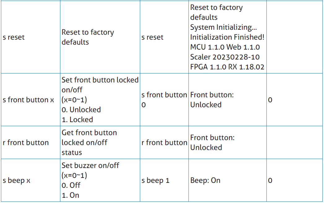


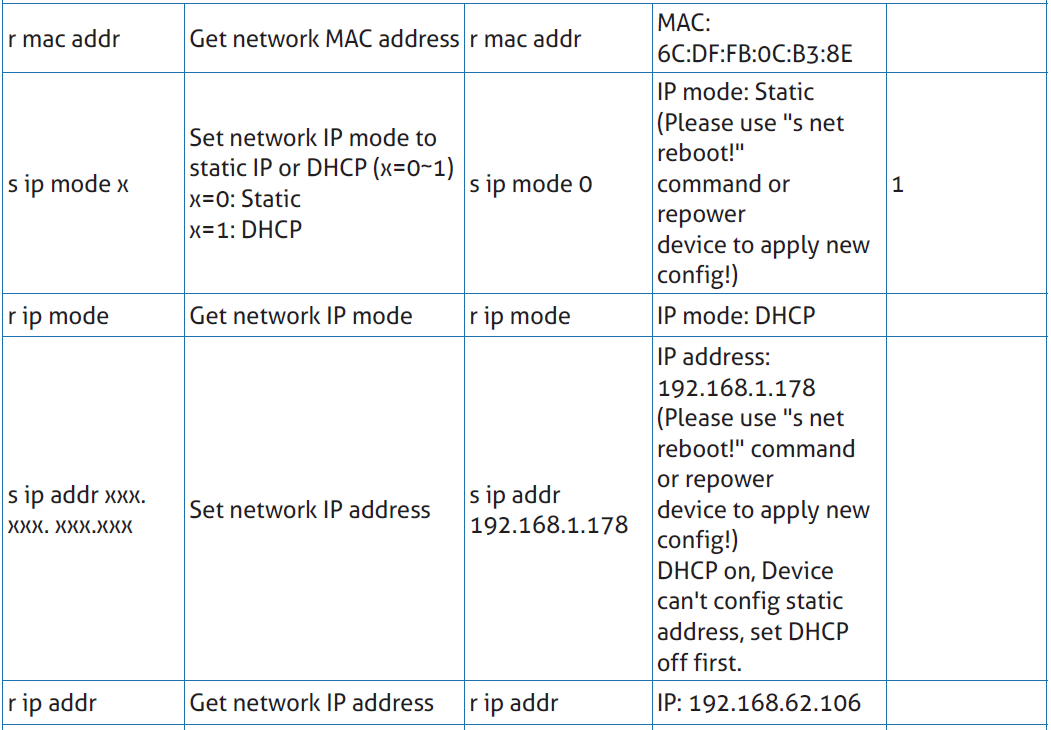

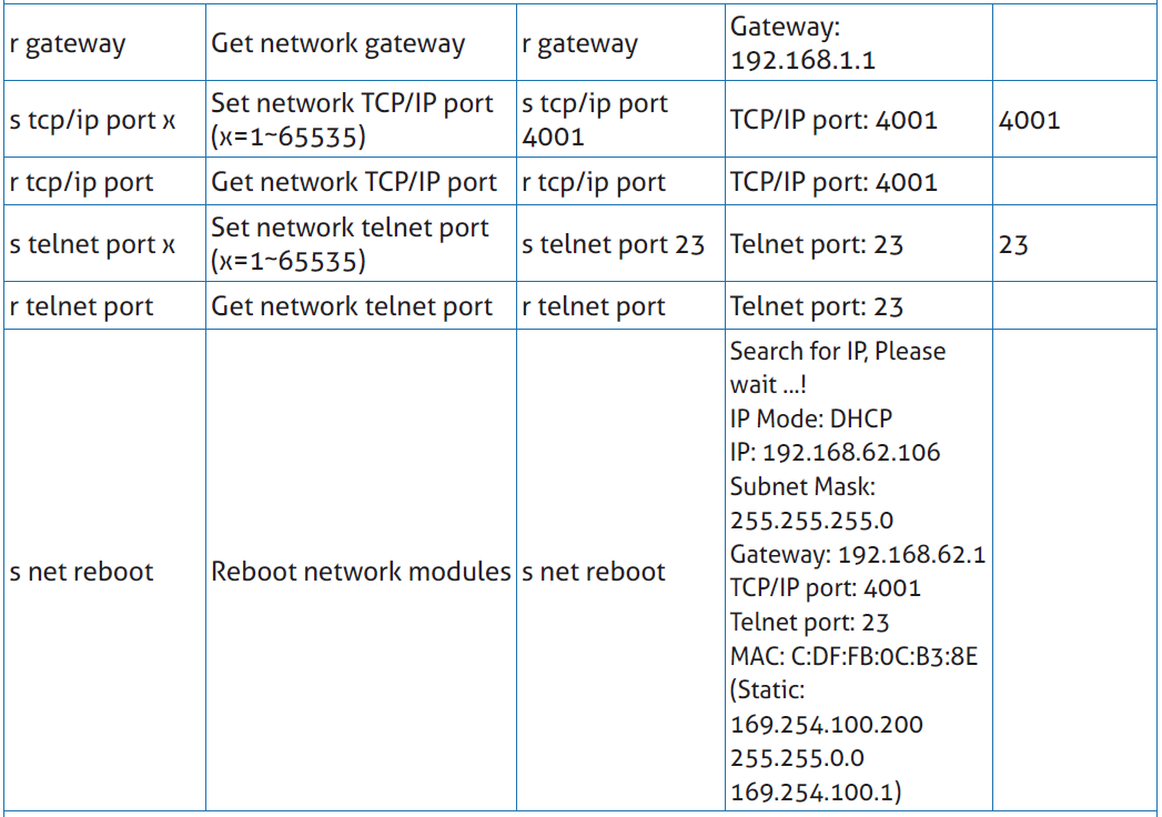

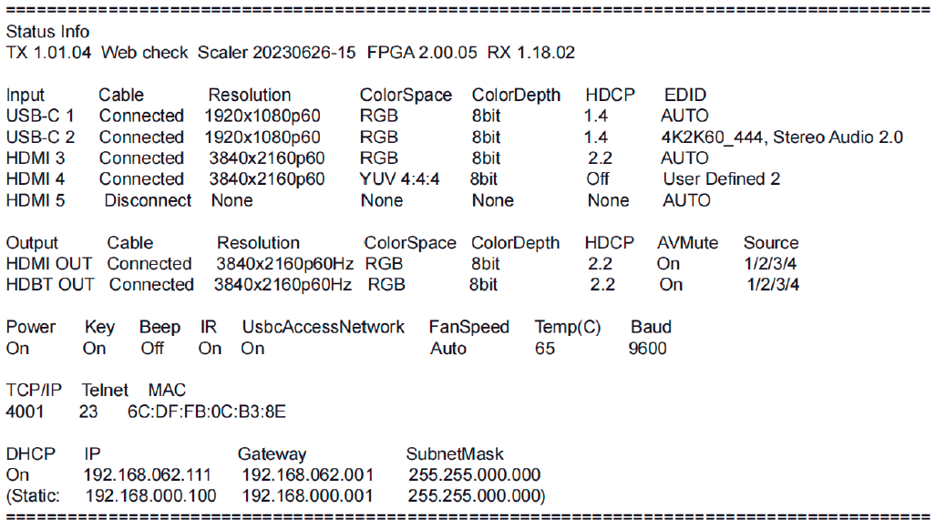
Note: The feedback of the command of “r status” is as following.
8. Usage Precaution
- Make sure all components and accessories included before installation.
- System should be installed in a clean environment with proper temperature and humidity.
- All of the power switches, plugs, sockets, and power cords should be insulated and safe.
- All devices should be connected before power on.
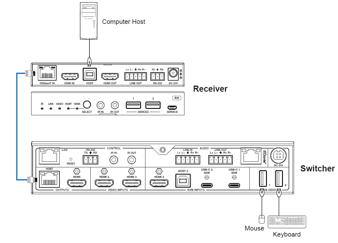
9. System Diagram
The following diagrams illustrate typical input and output connections that can be utilized with this device:
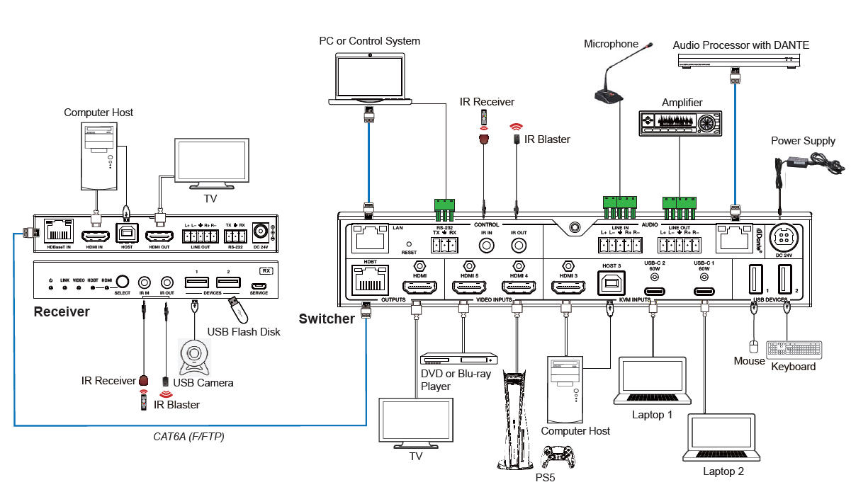
Note 1. The receiver has 2 modes - HDMI and HDBaseT.
Note 2. In HDBaseT mode the camera, touch screen, keyboard and mouse can all be controlled by the TX host PC.
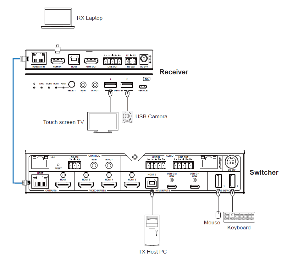
Note 3. When the Receiver is set to HDMI mode, The RX laptop ONLY has access to the touch screen and camera, but NOT the Keyboard and mouse.
Note 4. Key board control in HDBT mode - A host at the TX side can be controlled by mouse or keyboard attached to the RX.
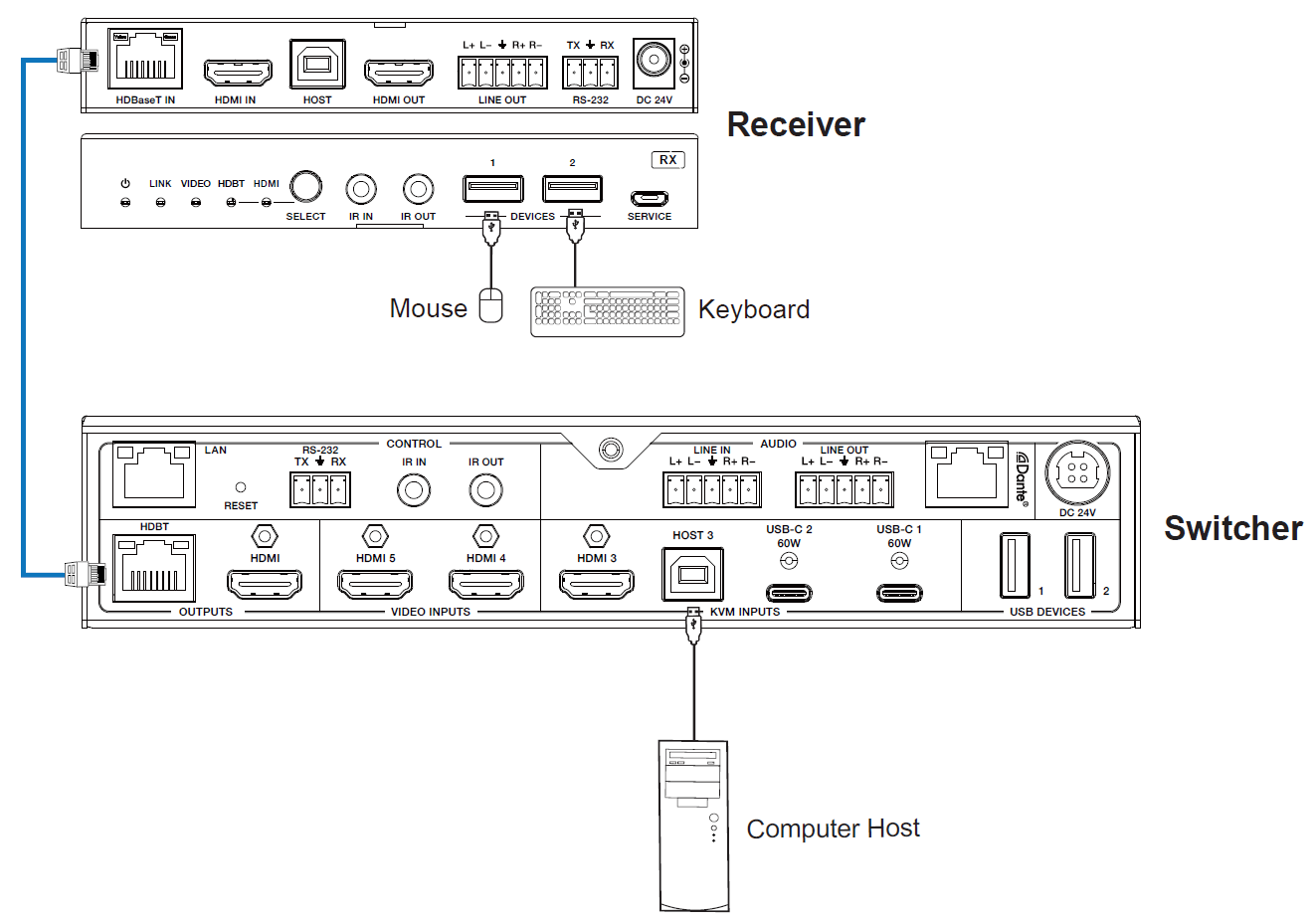
BUT a host at the RX side and a mouse or keyboard at TX side will not work.
10. After-Sales Service
If there appear some problems when running the product, please check and deal with the problems referring to this user manual. Any transport costs are borne by the users during the warranty.
- Product Limited Warranty:
This product will be free from defects in materials and workmanship for three years (The purchase invoice shall prevail). Proof of purchase in the form of a bill of sale or receipted invoice which is evidence that the unit is within the Warranty period must be presented to obtain warranty service.
- What the warranty does not cover (servicing available for a fee):
- Warranty expiration.
- Factory applied serial number has been altered or removed from the product.
- Damage, deterioration or malfunction caused by:
- Normal wear and tear.
- Use of supplies or parts not meeting our specifications.
- No certificate or invoice as the proof of warranty.
- The product model showed on the warranty card does not match with the model of the product for repairing or had been altered.
- Damage caused by force majeure.
- Servicing not authorized by distributor.
- Any other causes which does not relate to a product defect.
- Delivery, installation or labor charges for installation or setup of the product.
- Technical Support: For any questions or problems, contact your distributor or reseller and tell them the respective product name and version, the detailed failure situation as well as the formation of the cases.
Asking for Assistance
Technical Support:
Phone: +49 5971 800299 - 0
Fax: +49 5971 800299 – 99
Technical Support Hours:
8:30 AM to 5:00 PM Monday thru Thursday
8:30 AM to 4:00 PM Friday
Write to:
PureLink GmbH
Von-Liebig-Straße 10
D - 48432 Rheine
www.purelink.de
info@purelink.de